Monday 20 May 2013
Transistor Cheker
Transistor Cheker
Introduction :
Features :
¤ Small in size
¤ Easy to handle
¤ Nice design
¤ 9v battery powered
¤ Portable
¤ Very useful circuit
¤ LEDs give visual experience
¤ Long life
¤ Cheap circuit
¤ Easy to handle
¤ Nice design
¤ 9v battery powered
¤ Portable
¤ Very useful circuit
¤ LEDs give visual experience
¤ Long life
¤ Cheap circuit
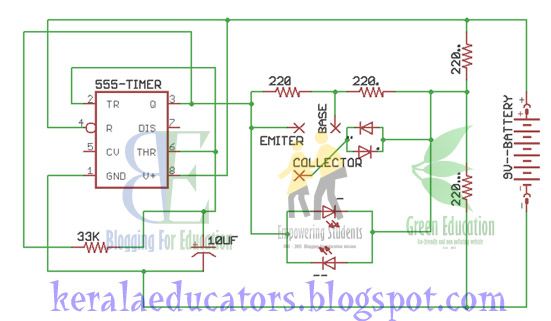
Circuit Diagram :
Components Required :
IC : NE555
Resistor : 33k
Resistor : 220
Resistor : 220
Resistor : 220
Resistor : 220
Capacitor : 10uF
Diode : 1N4007
Diode : 1N4007
LED : RED
LED : GREEN
Battery : 9V
Resistor : 33k
Resistor : 220
Resistor : 220
Resistor : 220
Resistor : 220
Capacitor : 10uF
Diode : 1N4007
Diode : 1N4007
LED : RED
LED : GREEN
Battery : 9V
Purchase DIY Kits :
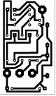
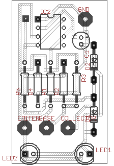
PCB Layouts :
Now Shipping Service is available only to Kerala and Tamil Nadu
It Is Closed Now! Please come back later
Available Images :
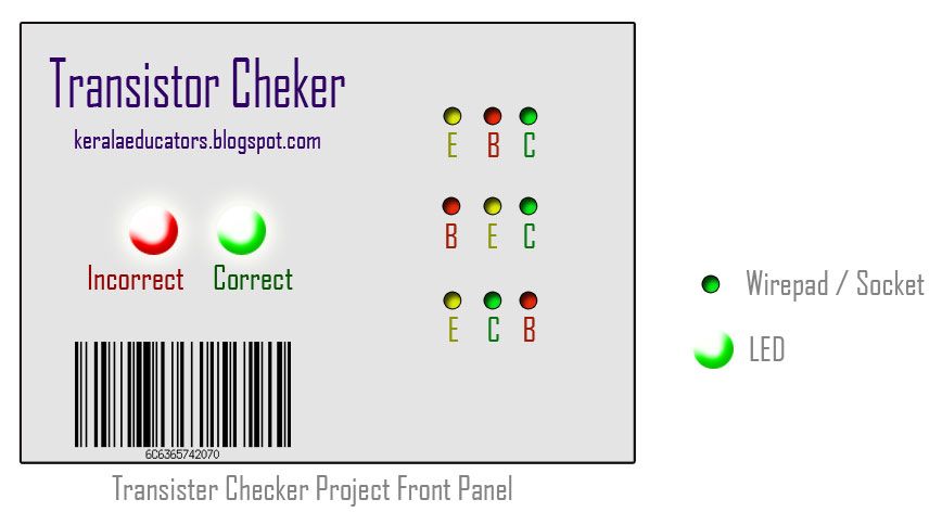
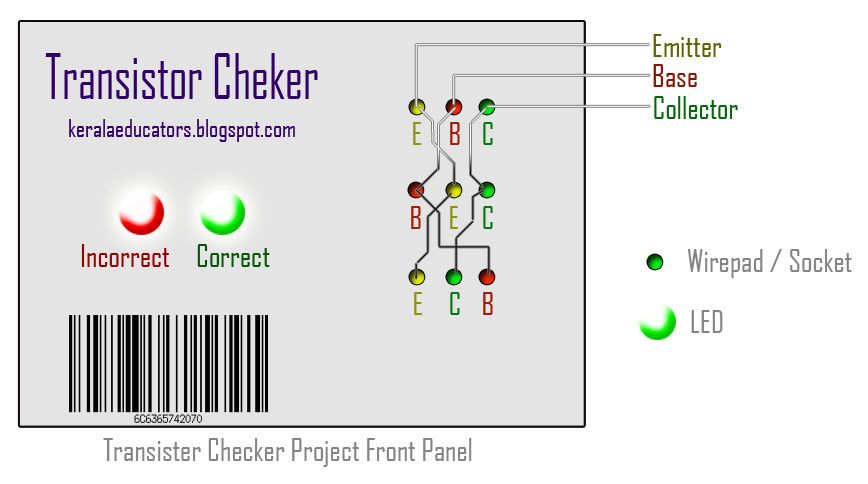
Transistor Cheker
This is a simple circuit for identifying leads of any transistor. It will show you whether transistor leads you connected are correct or not by glowing red and green LEDs. This circuit is done by a popular analogue integrated circuit 555. It is also small in size and cheap. This is a battery powered circuit and have long life. Here we published front panel of product. Circuit is so simple and similar to transistor tester.
In this project front panel that we published contains some wirepad or socket. It is for connecting transistors. I done it by cutting IC socket into 3 holes group an connected it on the case. By soldering it with appropriate connection i completed this project neatly.
I also used stickers to decorate the case.
Note : This image is shown as sample. You can make as per you design. It is also too large. Original board doesn't have this much size.
LED COLOUR ORGAN - 3 CHANNEL
LED COLOUR ORGAN - 3 CHANNEL
Introduction :
Features :
¤ Aura Design
¤ Portable
¤ No negative power supply needed
¤ Analogue for good fading effect
¤ 12 volts DC power Supply Needed.
¤ Low power consumption.
¤ Circuit with easily available components
¤ Supports mono and stereo
¤ Portable
¤ No negative power supply needed
¤ Analogue for good fading effect
¤ 12 volts DC power Supply Needed.
¤ Low power consumption.
¤ Circuit with easily available components
¤ Supports mono and stereo
Circuit Diagram :
Components Required :
Resistors :
47k x 3
1M x 1
1k x 5
360k x 3
680k x 3
39k x 3
100k x 5
470k x 2
160E x 2
20k Preset x 3
-----------------
Red LED x 4
Yellow LED x 4
Green LED x 4
47k x 3
1M x 1
1k x 5
360k x 3
680k x 3
39k x 3
100k x 5
470k x 2
160E x 2
20k Preset x 3
-----------------
Red LED x 4
Yellow LED x 4
Green LED x 4
Working :
Audio signal is connected to C1 which bypasses AC and block all DC content in the input audio signal. Next section is an inverting amplifier with Input Resistance 47K and Feedback resistance 1M. So, the voltage gain is 21.275 and inverted. Then it is connected to 3 sections for filtering through a variable resistor to select the input voltage of three. Next section is Band pass filter for Bass, Normal, Treble frequencies. Its output is filtered from DC and rectified. It is connected to the base of a NPN transistor and this NPN transistor dives LEDs Smoothly. The limiting resistor in series with LEDs provide high current flow protection.
All Non-inverting terminals are connected to a virtual ground network and through this idea we can avoid negative voltage to the op-amp.
All Non-inverting terminals are connected to a virtual ground network and through this idea we can avoid negative voltage to the op-amp.
Purchase DIY Kits :
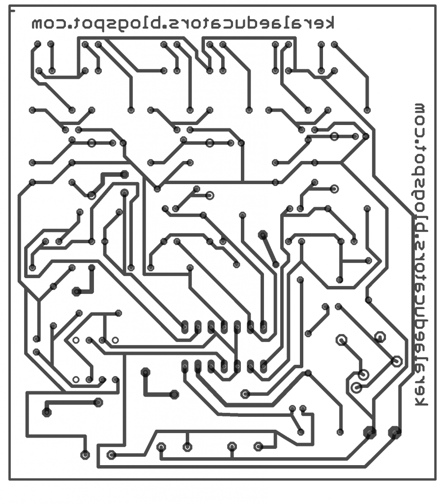
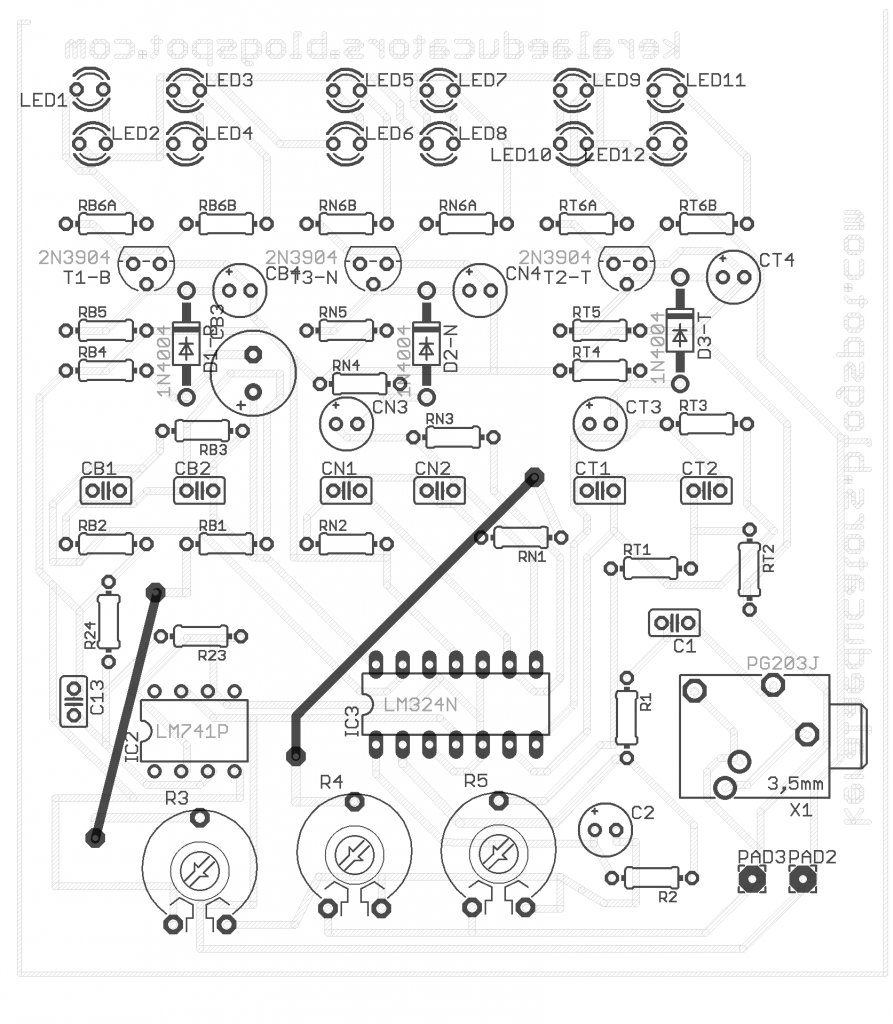
PCB Layout :
Fully Assembled and Ready made Board.
( You need to soldered )
( You need to etched and soldered )
Complete Components and blank PCB
Components Only
Complete Components and Ready made PCB
Now Shipping Service is available only to Kerala and Tamil Nadu

Cost: $2.24
Cost: $2.88
Cost: $3.45
Cost: $3.73
In Stock
In Stock
In Stock
In Stock
Incoming Search Terms:
LED Color Organ
Light Organ
3 Channel Spectrum
Mini Project
Electronic Hobby Circuits
Electronic circuits
Electronic Schematics
Electronic Projects
Simple Electronic Project
Circuits with PCB layout
PCB artwork
DIY kits
DIY kits supply on Kerala and Tamil Nadu
Simple Electronic Circuit
Project
Schematics
Circuit Diagram
Schematic Diagram
Electronic for students
Electronic projects for child
Available Images :
It Is Closed Now! Please come back later
Capacitors:
1uf x 3
4.7uf x 2
0.047uf x 3
0.1uf x 2
0.0022uf x 2
2.2uf x 3
22uf x 1
-------------
1N4007 x 3
2N3904 x 3
-------------
IC LM324 x 1
IC uA741 x 1
Sterio Jack 1
1uf x 3
4.7uf x 2
0.047uf x 3
0.1uf x 2
0.0022uf x 2
2.2uf x 3
22uf x 1
-------------
1N4007 x 3
2N3904 x 3
-------------
IC LM324 x 1
IC uA741 x 1
Sterio Jack 1
The dawn of digital music is visualized in the form of lights. But now they are mostly visualized through programming techniques. Here I present a project which visualized music by Light Emitting Diodes. First of all the credit goes to makezine blog where I grabbed this circuit and published. The more introduction will available a makezine blog. Here I am only presenting this project in front of you.
There is a Virtual Ground section in the circuit diagram. That means it needs to be connected with all non-inverting terminals of op-amp. Quad op-amp IC MC3324PG and Single op-amp IC TS921 are unavailable at my place. So i replaced both of them with LM324 and uA741. For this circuit both ICs will work fine. Components packs includes this both Ics and if you want to do this project in your home, please order the DIY kits from bottom of this page.
There is a Virtual Ground section in the circuit diagram. That means it needs to be connected with all non-inverting terminals of op-amp. Quad op-amp IC MC3324PG and Single op-amp IC TS921 are unavailable at my place. So i replaced both of them with LM324 and uA741. For this circuit both ICs will work fine. Components packs includes this both Ics and if you want to do this project in your home, please order the DIY kits from bottom of this page.
LED COLOUR ORGAN - 3 CHANNEL
Transistor Tester
Transistor Tester
Introduction :
Features :
¤ Small in size
¤ Easy to handle
¤ Nice design
¤ 9v battery powered
¤ Portable
¤ Very useful circuit
¤ LEDs give visual experience
¤ Long life
¤ Cheap circuit
¤ Easy to handle
¤ Nice design
¤ 9v battery powered
¤ Portable
¤ Very useful circuit
¤ LEDs give visual experience
¤ Long life
¤ Cheap circuit
Circuit Diagram :
Components Required :
IC : NE555
Resistor : 33k
Resistor : 220
Resistor : 220
Resistor : 220
Resistor : 220
Capacitor : 10uF
Diode : 1N4007
Diode : 1N4007
LED : RED
LED : GREEN
Battery : 9V
Resistor : 33k
Resistor : 220
Resistor : 220
Resistor : 220
Resistor : 220
Capacitor : 10uF
Diode : 1N4007
Diode : 1N4007
LED : RED
LED : GREEN
Battery : 9V
Purchase DIY Kits :
PCB Layouts :
|
Components Only
|
Cost : 00.00$
|
In Stock!
|
|
|
Complete Components and blank PCB
( You need to etched and soldered )
|
Cost : 00.00$
|
In Stock!
|
|
|
Complete Components and Ready made PCB
( You need to soldered )
|
Cost : 00.00$
|
In Stock!
|
|
|
Fully Assembled and Ready made Board.
|
Cost : 00.00$
|
In Stock!
|
|
Now Shipping Service is available only to Kerala and Tamil Nadu
It Is Closed Now! Please come back later
Available Images :
Transistor Tester
This is a simple circuit for testing any transistor. It will show you whether transistor is working or not by glowing red and green leds. This circuit is done by a popular analogue integrated circuit 555. It is also small in size and cheap. This is a battery powered circuit and have long life.
LED CHASER USING 555 TIMER
LED CHASER USING 555 TIMER
Introduction :
LED Chaser is a decorative project and easy to use. This circuit does not need any micro controller or complicated digital Ics. It is too simple circuits and any one can design. This circuit is designed by popular Analoge IC 555. It is too simple and very easy to create. Less components and small in size are some advantages of this project.
Features :
¤ Portable
¤ Simple Circuit
¤ Beautiful design
¤ Able to extent
¤ Works with 9V battery
¤ Speed Adjustable
¤ Excellent in frame designing
¤ Less power consumption
¤ Simple Circuit
¤ Beautiful design
¤ Able to extent
¤ Works with 9V battery
¤ Speed Adjustable
¤ Excellent in frame designing
¤ Less power consumption
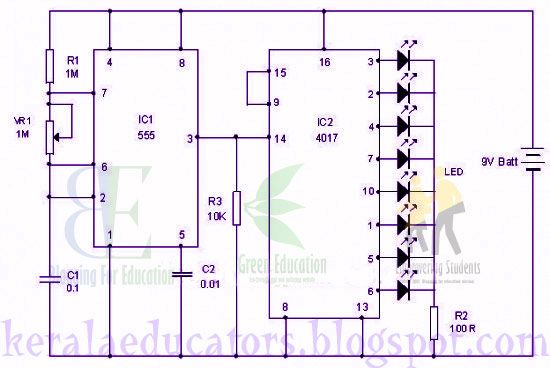
Circuit Diagram :
Components Required :
IC : 555 IC : 4017
Resistor : 1M
Resistor : 100k
Resistor : 10k
POT : 1000k
Capacitor : 0.01uf
Capacitor : 0.1uf
LEDs : 8 No.s
Battery : 9 v
Resistor : 1M
Resistor : 100k
Resistor : 10k
POT : 1000k
Capacitor : 0.01uf
Capacitor : 0.1uf
LEDs : 8 No.s
Battery : 9 v
Purchase DIY Kits :
Fully Assembled and Ready made Board.
( You need to soldered )
( You need to etched and soldered )
Complete Components and blank PCB
Components Only
Complete Components and Ready made PCB
Now Shipping Service is available only to Kerala and Tamil Nadu
LED CHASER USING 555 TIMER
Incoming Search Terms:
LED Chaser
Light Organ
555 projects
555 chaser
chaser
high speed chaser
low speed chaser
Mini Project
Electronic Hobby Circuits
Electronic circuits
Electronic Schematics
Electronic Projects
Simple Electronic Project
Circuits with PCB layout
PCB artwork
DIY kits
DIY kits supply on Kerala and Tamil Nadu
Simple Electronic Circuit
Project
Schematics
Circuit Diagram
Schematic Diagram
Electronic for students
Electronic projects for child
PCB Layout :
Cost : 1.32 $
Cost : 1.42 $
Cost : 1.51 $
Cost : 1.66 $
In Stock!
In Stock!
In Stock!
In Stock!
It Is Closed Now! Please come back later
Tuesday 14 May 2013
Complete A Survey!
.
.
.
.
.
.
.

.
.
.
.
.
.
.
.
.
.
.
.
.
.
.
.
.
.
.
Thank you for your interest to complete a survey. Here we provide a list of surveys and you want to sign up in that survey.
The first page of the selected survey contains the information about survey.
May be that is a website of shopping and you need to sign up that website and verify your email address. Then you will receive a coupon code or offers etc
May be it is a software website and you need to download that software and install it in your system. After installing that software survey completes.
May it is a online games website. You need to register and play that game registration may need to verify email address. Sometimes it needs only registering. Different surveys are in different ways.
May be it is an opinion survey. So you need to fill forms and share your valuable opinions about any brands, products, companies etc.. that the survey is referring to. First page they collect your information to check whether you are qualified or not.
Survey will open in new tab and in the previous tab you can check the status of survey whether it is completed or not. Close the survey only when the survey completed dialogue is shown in previous tab.
If you don’t get idea of survey that you taken, close that survey and try another survey.


Each survey is limited in 5 minutes. So do fast and reach the end immediately when you started the survey. You can use additional tricks to complete a survey like opening your email inbox before completing survey. Copying pasting etc…
Complete A Survey!
We hope you are interested in completing one.
Sunday 30 December 2012
Free Seeds
Free Bies Page
Woah! Now a Free stuff is available. Which is verified by most users and getting high traffic. Details are given below.
Name:
Offering Website:
Rating:
Details:
Everlasting Offers
(with Gifts)
(with Gifts)


Free Mobile Recharge of Rs.25
Free Bies Page
Woah! Now a Free stuff is available. Which is verified by most users and getting high traffic. Details are given below.
Offering Website :
Rating :
Details :
Everlasting Offers
(with Gifts)
(with Gifts)
Name :
Subscribe to:
Posts (Atom)

